The new RF Explorer for Windows v1.15.1610 is available (link)
It comes with important enhancements and fixes, recommended for all RF Explorer users:
- Delta Markers (Spectrum Analyzer and SNA)
- Markes can be placed anywhere on a trace using mouse double-click
- RF Data Sniffer (Beta)
- Latest OpenGL and 2D libraries upgraded including several bug fixes
- Fix for SNA tracking where sometimes reject first normalization scan with a warning due to low level signal (-80dBm warning). This is now resolved and you should be able to complete your normalization in one single step.
- Better grid scale display with thicker lines for major data points
- Performance improved in narrow scan display
Working with new Delta Markers
These are powerful tools to measure frequency and amplitude difference between two trace points. Usual workflows are Harmonic dBc measurements, relative channel transmission levels, noise figure, etc.
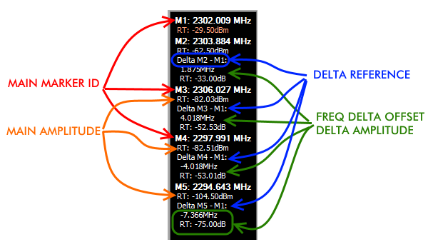
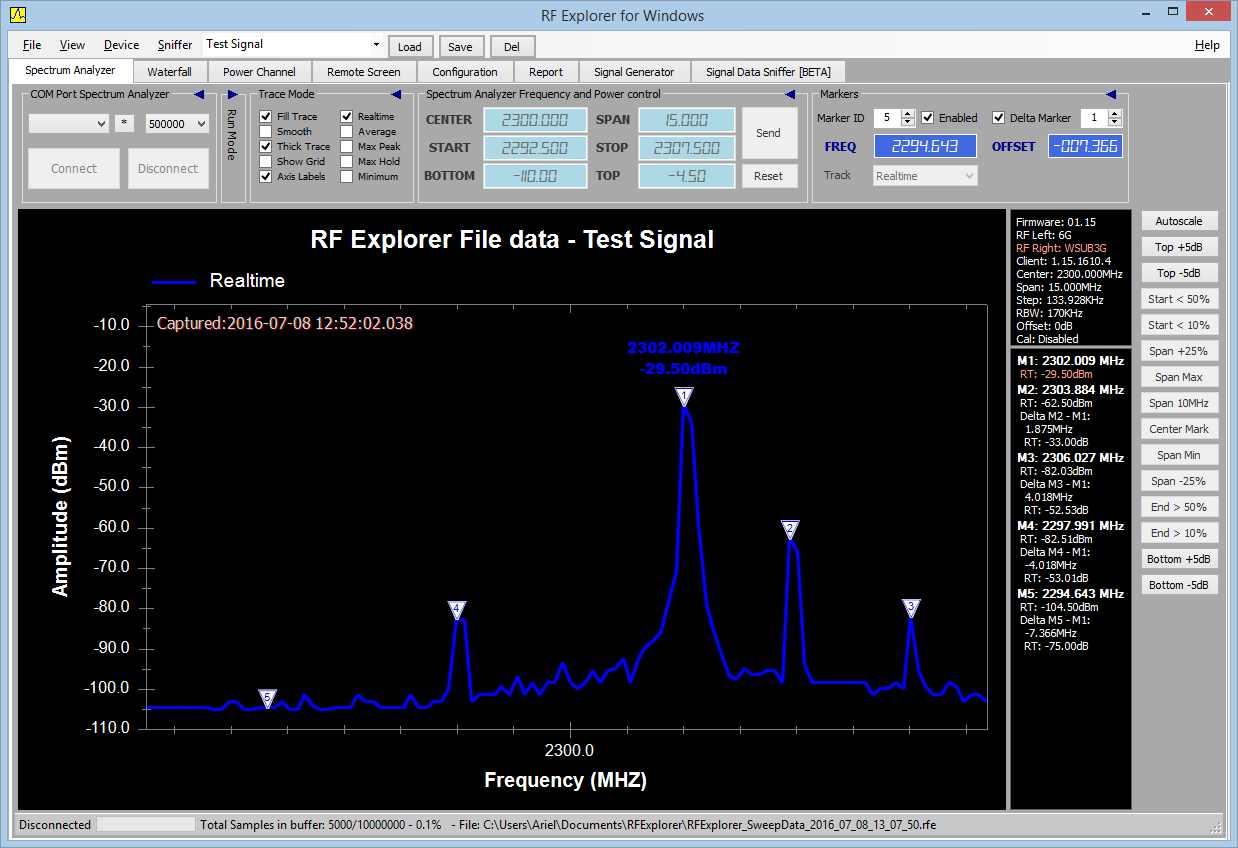
In this example above there are 4 markers defined as Delta (M2 to M5) and one Standard marker (M1). Any marker can be defined as delta from other reference markers.
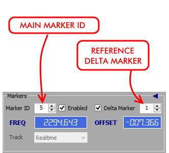
To define a Delta marker, first select the main Marker ID you want to define Delta link with. In this example below, Marker ID 5 is the Main marker, and Delta reference is Marker 1. That means frequency offset and amplitude will be calculated on screen as M5-M1. The M5 marker can be defined as an offset frequency from Marker 1 in this example, -7.366MHz.

On the right panel, the marker information display all detailed parameters:
- Standard amplitude absolute value for the marker (-104.5dBm)
- Delta definition (M5 – M1)
- Delta frequency: -7.366Mhz
- Delta amplitude: -75dB

If there are additional traces on screen, such as Average or Max, each one will list its own amplitude delta.
The Markers Display Panel has been updated to highlight in bold the Main Marker ID and current Frequency, and indent standard and delta values for easier visualization.
Some examples below:

Selecting a Delta Marker
- To define a Marker Delta, you first need a standard marker enabled. As an example, enable Marker 1, we will use it as Delta marker later.
- Increase Marker ID to go to Marker 5, enable it at any arbitrary frequency
- Check the Delta Marker and set the ID to 1
- At this point, Marker 5 is linked to Marker 1 and will display Delta calculations automatically
- Define offset in MHz you want Marker 5 to be from Marker 1. For instance, set it to -1Mhz, or 15Mhz, etc. Changing the offset will redefine position for Marker 5 based on current position of Marker 1.
Notes:
- Special Marker 1 can be Delta Marker of any other, but it cannot have associated any Delta Marker by Offset. The reason for this is Marker 1 works as auto-peak therefore cannot be defined as reference of any other.
- Markers defined by Offset use the value at the time of Marker definition, but does not update or keep that offset fixed if the Delta Marker changes frequency. For instance if you define Marker 5 at an offset of 5MHz of Marker 1, and marker 1 is currently at 100MHz, then Marker 5 will be located at 105Mhz. If Marker 1 moves to a different frequency later, Marker 5 will remain at 105Mhz, you can see the current frequency offset any time in the marker display panel.
- Future upgrades will allow for optional dynamic markers where offset will be locked so Main Marker absolute frequency value can change accordingly to the Delta Marker.

