IMPORTANT: Do not connect to 5V Arduino boards, the IoT module is only compatible with Arduino 3.3V models. Not following this advise will damage your IoT module.
For Seeeduino board, please select the correct power switch mode to work at 3.3V. You will damage the IoT module if the Seeeduino is configured for 5V.
Check Seeeduino configuration details from Seeedstudio wiki link.
Note: for other compatible and supported Arduino models, please check IoT for Arduino page link.
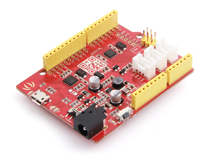
Connecting to a Seeeduino board
RF Explorer 3G+ IoT modules fit on a Seeeduino board, but two pin headers for TX3/RX3 will not be connected.
The main limitation of Seeeduino (and other small form-factor Arduino boards) is they support only one UART. Because this limitation, there is no direct way to monitor results in UART with Arduino Serial Monitor; the only available UART is used by the IoT module. This is the main reason Arduino Due is a better platform for IoT modules: it includes multiple UARTs and has a higher performance CPU with higher speed and memory.
Despite the limitations, you can work with Seeeduino in multiple projects. The advantage is lower power consumption, so it may be the ideal choice for certain projects. Optionally, you can get a second UART connection by using a separated USB CP2102 module as described later.
Prerequisites
In order to use RF Explorer 3G+ IoT shield you need:
- Seeeduino configured to 3.3V
- RF Explorer 3G+ IoT for Arduino
- USB Cable to upload sketch to Arduino from your Computer
- Recommended: USB CP2102 device for second UART (monitoring and debug)
- Latest Arduino IDE from official website
- RF Explorer 3G+ Arduino library: download from this link or visit the GITHUB site
Adding a monitoring / debug Serial connection
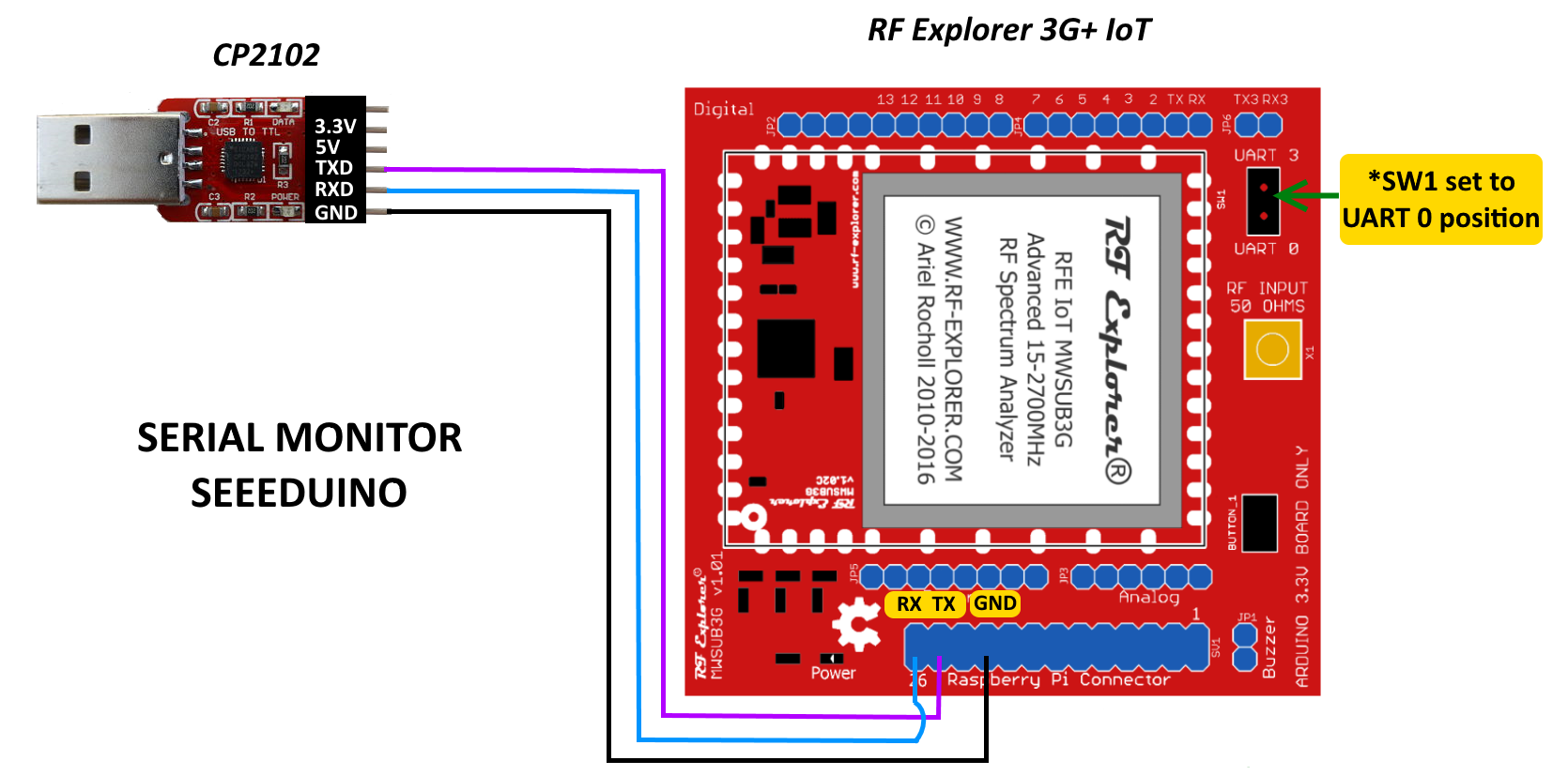
By using a low cost, readily available USB CP2102 device (soon available at Seeedstudio bazaar) you can get a monitoring serial connection.
There are only 3 cable connections required, we suggest to solder male header on the Raspberry Pi connector position and use direct cable connection to them, as depicted below.
The USB CP2102 device is also required for RF Explorer 3G+ IoT firmware upgrades (details coming soon).
Software Libraries
The RF Explorer 3G+ IoT libraries for Arduino are high performance, native Arduino libraries you can use in your projects. Library is free, open source code you can also modify for your own needs.
- Library reference wiki: link
The library is in constant development so you may want to check the latest available version.
Instructions:
- Download the library
- Decompress the zip file and copy the contents to the standard Arduino libraries folder location, typically c:\Program Files(x86)\Arduino\libraries in Windows.
- Open some of the examples
- Compile and upload to your Arduino board
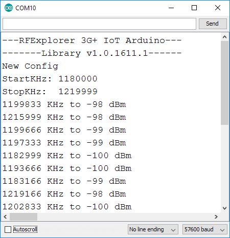
- Sketch example will run automatically after upload, you will need Arduino Serial Monitor to display text results and a separated USB CP2102 configured at 57600 bps
Arduino IDE setup
Seeeduino need some specific configuration setup, unrelated to RF Explorer, to properly work with all native Arduino libraries and examples.
Please follow detailed instructions from SeeedStudio wiki for correct setup.
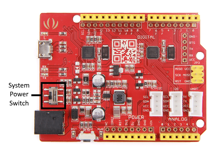
Please make sure your Seeeduino is configured at 3.3V (not 5V) - in the latest Seeeduino v4.2 is located in below "System Power Switch" mark.
Connect USB cable to the Seeeduino USB Port, and select the right board as described.
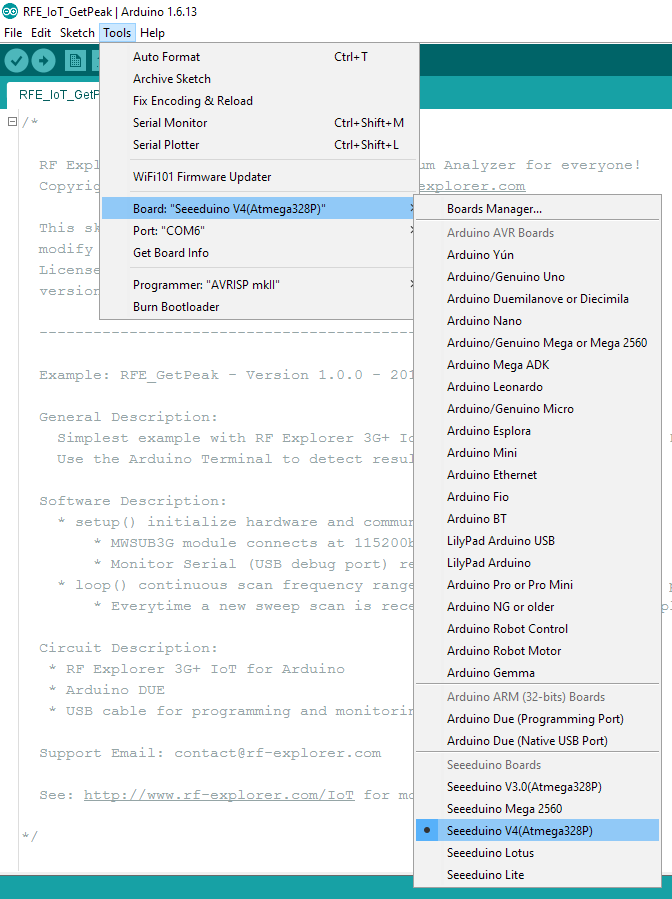
Last but not least, check the Tools->Port is correctly identified by the COMx port
Details on how to use examples
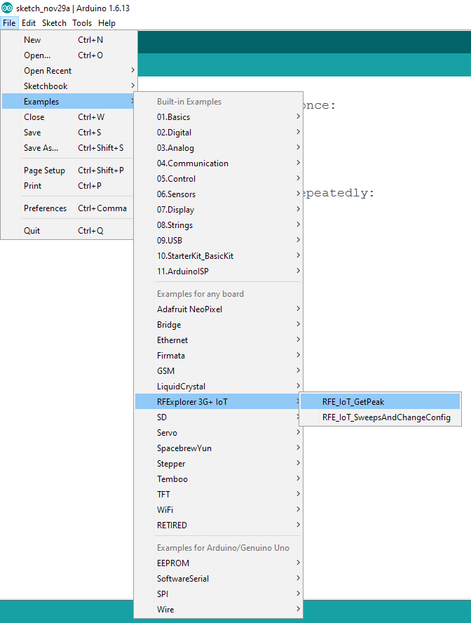
Run the Arduino IDE, and navigate through the File->Example->RF Explorer 3G+ IoT.
Select the RF Explorer 3G+ IoT switch SW1 to the position UART3. This is required before uploading sketch otherwise the UART will conflict with IoT module and will not upload.
You can see examples such as RFE_IoT_GetPeak or RFE_IoT_SweepAndChangeConfig.
Once the sketch upload is completed, set the RF Explorer 3G+ IoT switch SW1 to the position UART0. This is required for the UART to properly communicate with the IoT module after sketch is uploaded.
To monitor example activity and results, you need a USB CP2102 connected as described before. Connect the USB CP2102 to your computer and open Arduino Serial Monitor connected to the COM port.
Reset the Seeeduino board so the sketch starts from the beginning. Example results are displayed on the Arduino Serial Monitor