
This article describes the specific steps required to assemble an expansion module into a RF Explorer Signal Generator. For Spectrum Analyzer models, please visit the main article at www.rf-explorer.com/expansion
Depending on the RF Explorer model you have, you may need to order a separate top aluminum CNC cover. Please check this product from SeeedStudio for more details.
Adding an Expansion Module to RF Explorer Signal Generator is an easy but delicate task, please follow the process with care to details to make sure everything works fine after the assembly.
Important: After assembling of the RF Explorer Signal Generator Expansion board into a RF Explorer Signal Generator RFE6GEN baseline mainboard, the device becomes fully compatible with a RF Explorer Signal Generator Combo (specifications). Same specifications will apply for harmonics filtering, frequency accuracy and RF capabilities as a Combo unit assembled and calibrated at factory. However, due to differences between mainboard electronics, the RF power level accuracy cannot be guaranteed and may not comply with RF Explorer Signal Generator Combo specifications. We offer calibration services to fully adjust to specifications, please use contact form to request more information.
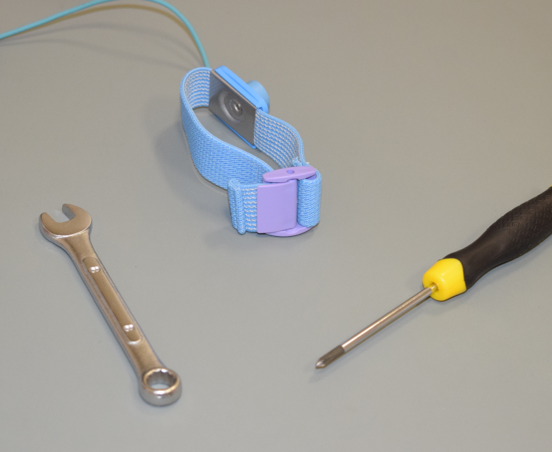
As you will be dealing with ESD sensitive electronic CMOS components, you need to use antistatic protection to avoid any impact on the circuit. For that, it is recommended to use an Antistatic wrist strap. Below is a picture with tools you will need to complete the task.
Before following this process, be sure you upgrade the RF Explorer firmware the latest available version from the download page. The firmware upgrade must be done before you install the hardware Expansion Module.
Take the RF Explorer case apart
The very first step is to power off your RF Explorer and disconnect it from any external USB source or power.
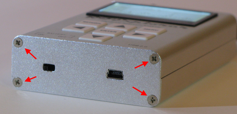
Get these 4 screws marked with red arrows out. Use an appropriate Philips screwdriver of the right size to avoid damaging the screws.
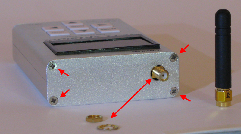
Then remove the antenna, the SMA nut and washer. Remove also the 4 screws marked with red arrows below.
If your model include 4 screws in the back cover, remove them as shown below (use this as reference image only, the antenna and covers won't be there if you followed above steps). If your model does not include these screws, you can safely go to next step.
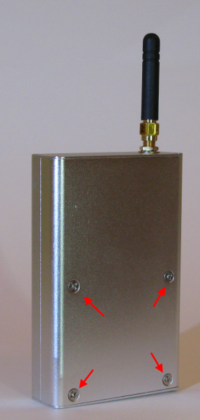
You probably need a different (larger) Philips screwdriver for these screws when compared to those of the top cover.
Plug the Expansion Module in
You can now get the PCB out of the enclosure, you may optionally disconnect the lipo battery but that is not mandatory if you keep the power switch in the OFF position at all times.
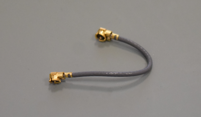
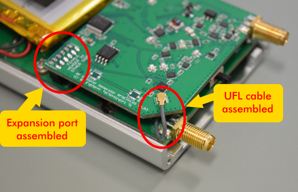
The first step is to connect the small UFL cable to the mainboard. First shape it the way shown in the picture for easier assembly. Important: the UFL cable should be handled with care and never forced or twisted.
This UFL cable must be connected to the UFL connector on the Signal Generator mainboard:

Important: Check the UFL connector is clean and has no dust or metal particles. If it is not clean enough, use an antistatic small brush and compressed air to clean the connector.
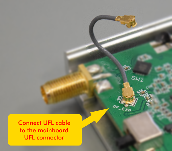
Important: If the UFL cable needs to be reconnected, never pull the cable as you will certainly damage it. The UFL cable must be removed by using small tweezers over the cable connector itself, not pulling the cable.
Once the UFL cable is correctly connected, the next step is to locate the digital Expansion port. See marked in red the 12 position 2mm male header connector on the mainboard PCB:
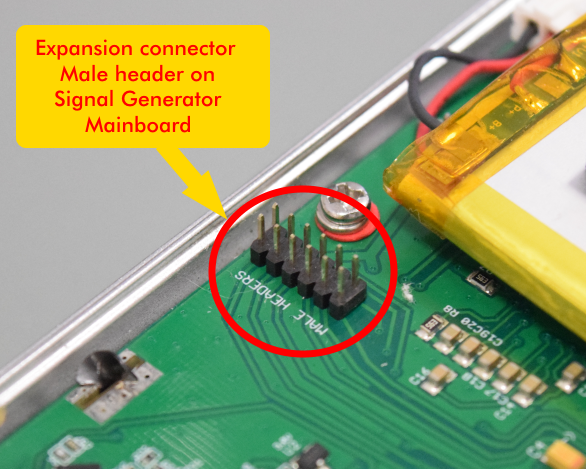
This is where the female 12 position 2mm connector from the Expansion Module must be connected
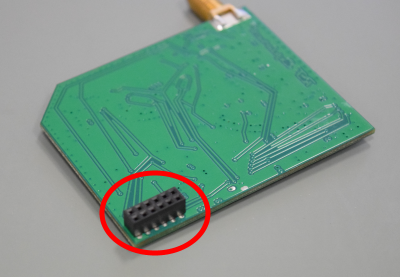
and once firmly plugged in should fit as shown below. This is the point in which the new module is already electrically connected to the main board.
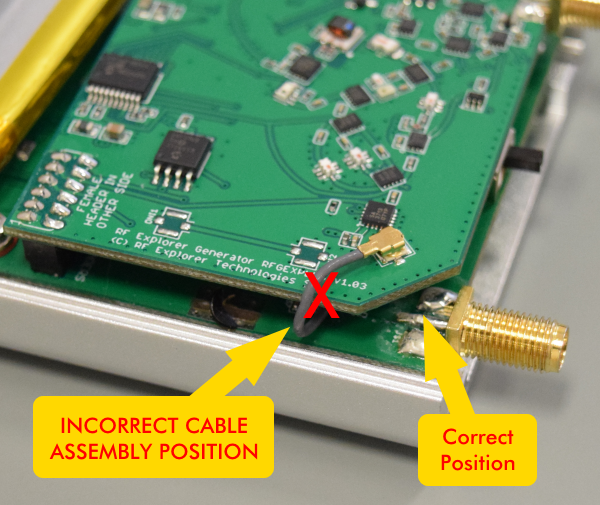
Please note the cable position should go exactly as pictured in previous image. The PCB corner is specially adapted to fit the cable in a secure location, far from the enclosure edge that otherwise may damage it. See below an example of incorrect cable position.
Important
Review very carefully your battery is not making contact with any PCB or connector anywhere.
The battery should have been assembled in the Fab in such a way that would be in an area far from the Expansion Module contacts. However, if you see the battery in risk of contacting the PCB, connector or anything else, you will need to fix that before assembling the RF Explorer. The battery is glued to the bottom cover as well as secured in place with Kapton tape, you should not modify that except by contacting with us first.
Always proceed very carefully with the Lithium Ion battery and make sure it is not punctured, damaged or inflated in any way. A healthy battery is a flat rectangle with no signs of any deformation. If you have any doubt, please take a picture of your unit and send it to us for further help. Read this article for additional information on battery handling and care.
Assemble RF Explorer
It is time to reassemble the unit now. Next step is to securely attach the back cover to the PCB, making sure the UFL cable is correctly in place as described. The Expansion connector should be secured in place with a foam pushing the back cover towards the expansion PCB.
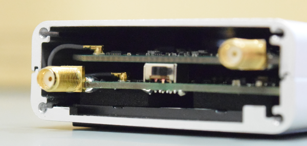
Then fit the front cover and ensure the Expansion Board is aligned with the PCB. At this point the only point of contact is the PCB connector, so manipulate it with care to not disconnect it unintentionally. Once you fit the top cover with the SMA nut it will get mechanical strength needed for operation. Note the correct position of the UFL cable.
Allocate the next 4 screws and the SMA nuts and washers.
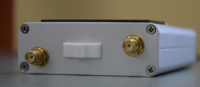
The SMA nuts should be secured firmly to give the internal PCB the required mechanical stability. Once everything fits in place, you should use a wrench (5/16 inch or 8mm) to secure the SMA nuts (not too strong, but not loose). Last screws are the ones on the bottom cover, and you are all set. Final step is to tighten all screws up in all top, bottom and back covers.
As the unit is expected to already have the latest firmware installed, you can now power the unit on, if everything is working as expected, you will see a screen detailing the base model and new module in place. Check the new module is identified as expected.
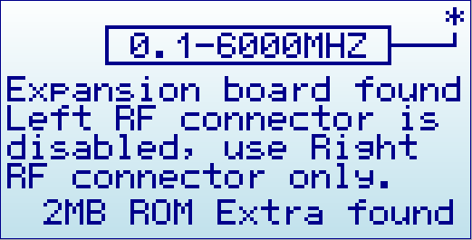
The asterisk mark indicates the SMA connector associated with the module.
Notes:
- There may be minor variations in the pictures shown when compared to what you have, based on model or production batches. If you got any question, please ask in the list or by the contact form.
- All the RF Explorer CNC job is done with sub-millimeter accuracy. It may be sometimes difficult to fit everything perfectly in place if you tighten some screws too much before having the others in place. You may need to release a bit some screws for the others to fit properly in place. Generally speaking, it is better to have all the screws in place before you tighten them up to their final position.
- Depending on the RF Explorer model you have, you may need to order a separate top aluminum CNC cover. Please check this product from SeeedStudio for more details.