
But let’s use the RF Explorer Windows PC Client to see this with better detail, in full color. Open it while the RF Explorer is connected to the USB port. Start with 24 iterations as we did in the RF Explorer, and check mark Max and Average only (we don't need Realtime nor Min values for this research, but you are free to activate and play with them as well).
You should get something like this (click on the image to enlarge it to full size):
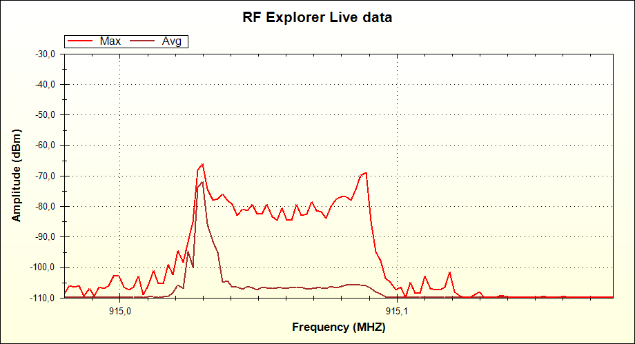
And that is really interesting.
The PC client, thanks to a better screen, show us the Max signal spectrum envelop as we saw it initially in the RF Explorer screen, but at the same time the Average value show us very clearly how the “zero” peak is way more frequent than the “one”. We are looking in the same graph, with great clarity, what we did in the RF Explorer screen with two different configurations. You know.... the PC is here to help!
Now, if our interpretation of the modulated signal is correct, we should see just the opposite behavior when the RFBee transmit packages with ones, and not zeros…. Let’s check that: simply unplug both cables from port 2 and 3 out of GND, making them both high at the same time.
At that point, the RFBee will start transmitting this
10101010 - 11111111
[preamble] [payload]
And we should see a behavior change in the signal spectrum shape.
And that is exactly what we get; after a few iterations the calculator stabilizes and this is the new shape:
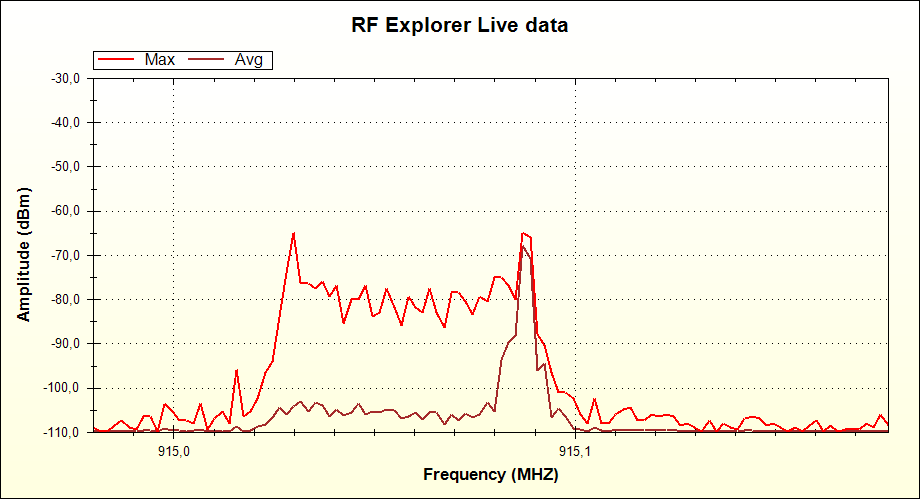
Now the higher averaged weight goes to the ones side as expected.
Can we distribute a modulated signal with equal number of zeros and ones?
Absolutely, just plug the port 3 only to GND, and keep the port 2 unplugged. After calculator stabilizes, you will see this
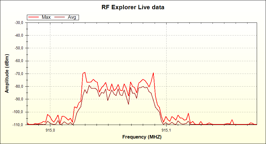
Now both peaks are weighted the same by the average calculator, because we are now transmitting this pattern from RFBee:
10101010 - 10101010
[preamble] [payload]