
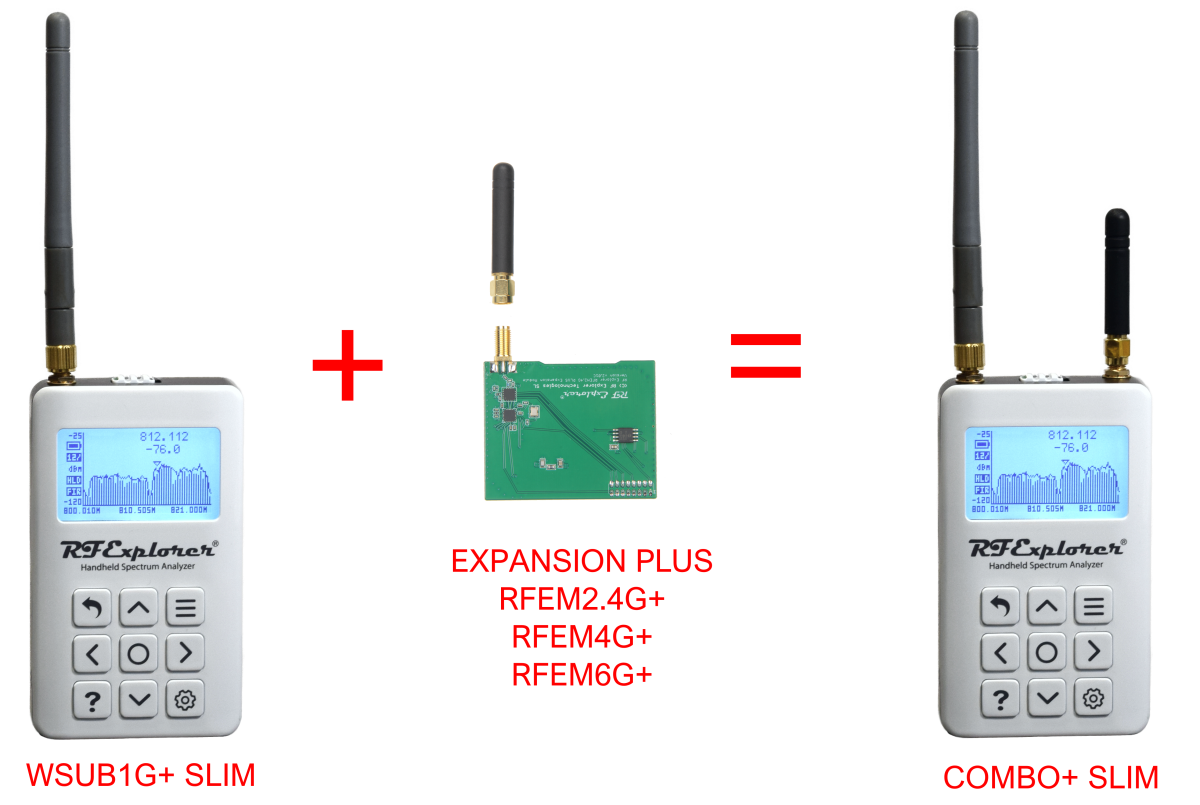
Use these instructions to assemble a RFEM2.4G PLUS, RFEM4G PLUS or a RFEM6G PLUS into a RF Explorer WSUB1G PLUS SLIM unit.
For RF Explorer WSUB1G PLUS with older enclosure please use this alternative article.
Firmware support for expansion modules requires version 3.16, available in our download page. Please follow below instructions to assemble the expansion module in your RF Explorer WSUB1G PLUS spectrum analyzer.
Upgrade Firmware
Before following this process, be sure you upgrade the RF Explorer WSUB1G PLUS firmware with the v3.16 or latest available version from the download page. The firmware upgrade must be completed before you install the hardware Expansion Module.
Failing to upgrade firmware may result in configuration issues and not recognizing the expansion board.
Important: due to configuration data format, after upgrading to v3.16 you must not downgrade to an earlier version as otherwise calibration data may be lost in your unit.
ESD precautions
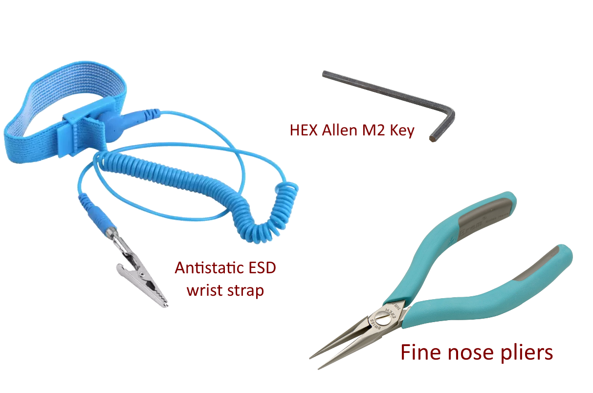
As you will be dealing with ESD sensitive electronic CMOS components, you should use antistatic protection to avoid any impact on the circuit, and handle carefully not making finger contact with any electronic component.
It is strongly recommended to use an Antistatic wrist strap properly grounded. See below tools you will need for the upgrade.
Remove RF Explorer case cover
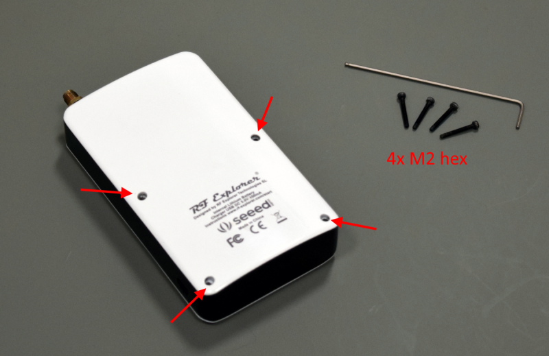
The very first step is to power off your RF Explorer and disconnect it from any external USB source or power.
Next step is to remove the 4 hex screws using a M2 allen type key.
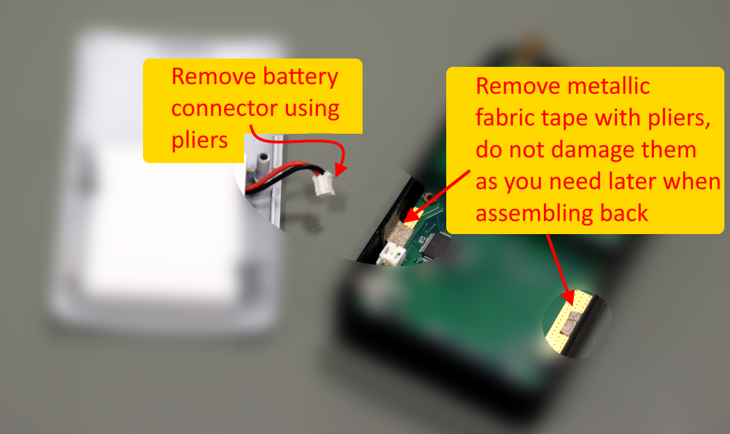
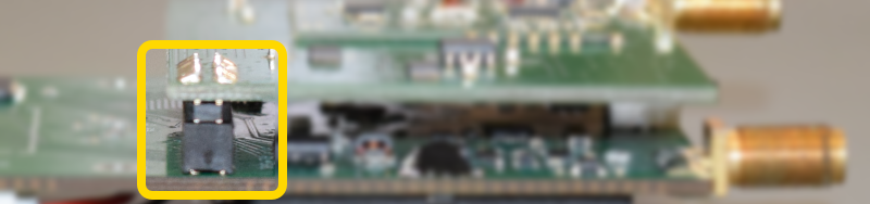
Disconnect battery carefully using fine pliers, then remove the metallic tape from the PCB and middle cover.
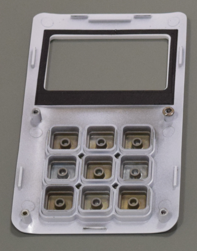
Pull the PCB and middle cover back to free the front cover in this horizontal position, so all the keyboard keys remain in the right position.
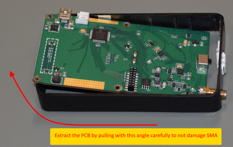
At this point the black metallic middle cover is free to remove the PCB. First remove the SMA nut and washer, then pull the PCB as shown below
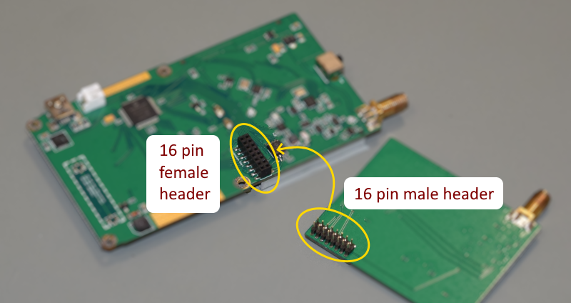
Plug the Expansion Module in
You can now get the PCB out of the box, you may optionally disconnect the lipo battery but that is not mandatory if you keep the power switch in the OFF position at all times.
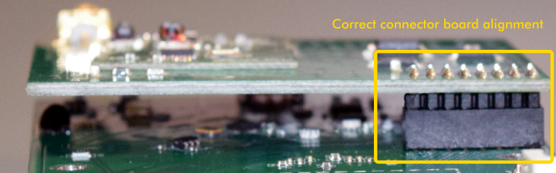
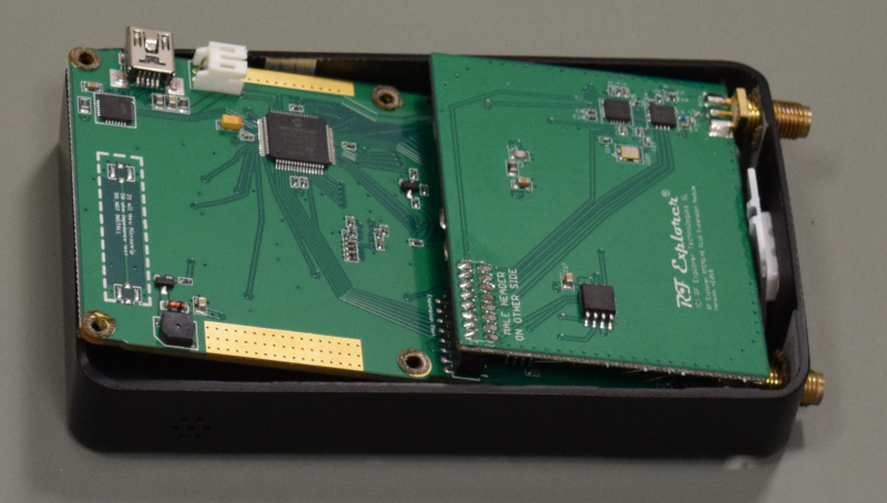
After proper connection, the alignment of the boards must look like these images below.
Important
- Review very carefully your battery is not making contact with any PCB or connector anywhere.
- The battery should have been assembled in the factory in such a way that would be in an area far from the Expansion Module contacts. However, if you see the battery in risk of contacting the PCB, connector or anything else, you must fix that before assembling the RF Explorer unit back.
- Always proceed very carefully with the Lithium Ion battery and make sure it is not punctured, damaged or inflated in any way. A healthy battery is a flat rectangle with no signs of any deformation. If you have any doubt, please take a picture of your unit and send it to us for further help. Read this article for additional information on battery handling and care.
Assemble RF Explorer
Remove the rubber hole cover to free the SMA on the right side, and correctly put the power switch cover in place.
Then use the angled position to assemble the PCB back into the middle cover.
Once the PCB is back in the right position, follow this order to finish the assembly:
- Put the middle cover on top of the front cover horizontally, so all keys remain in the right position.
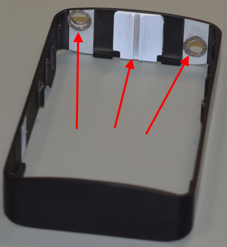
- Get the metallic fabric tape correctly located in their original position, making sure are only using their designated area and not making any electrical contact with components or vias outside the ground marked area.
- Double check the power switch is in the off position (black mark)
- Connect the battery
- Assemble back cover and use the 4 screws
Power the unit on, if everything is working as expected, you will see a screen detailing the base model and new module in place. Check the new module is identified as expected, below is an example but the exact screen will depend on the model installed.
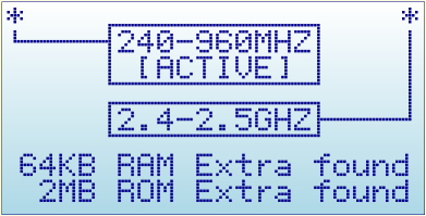
The asterisk mark indicates the SMA connector associated with the module, and the [ACTIVE] signals the currently actived one.
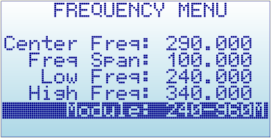
You can use the MENU button to navigate to this screen anytime to review your configuration. To switch between the two available modules, you can use the MENU button to navigate to the FREQUENCY MENU and then cycle through the active module by clicking ENTER on the Module option at the bottom.
Notes:
- There may be minor variations in the pictures shown when compared to what you have, based on model or production batches. If you got any question, please contact us using the contact form.
- We can do fully assembly for you in our lab for a small extra charge, contact us if you prefer that option.